In view of the little info about balancing cranks I could find, here's a quick low-down on how one firm do it - this is Julian Escuret of Escuret Rectification in Montpellier, France, in action on my A+ 1275 crank.
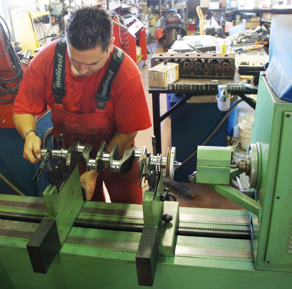
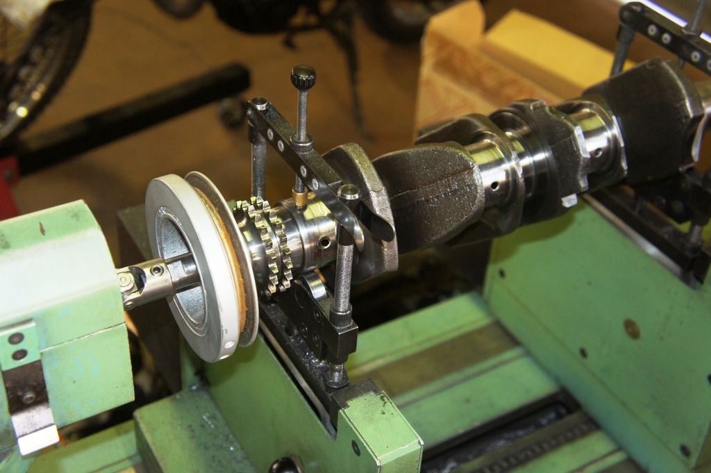
The crank is driven via a UJ bolt that replaces the Mini crank-damper bolt, and initially without any flywheel/clutch.
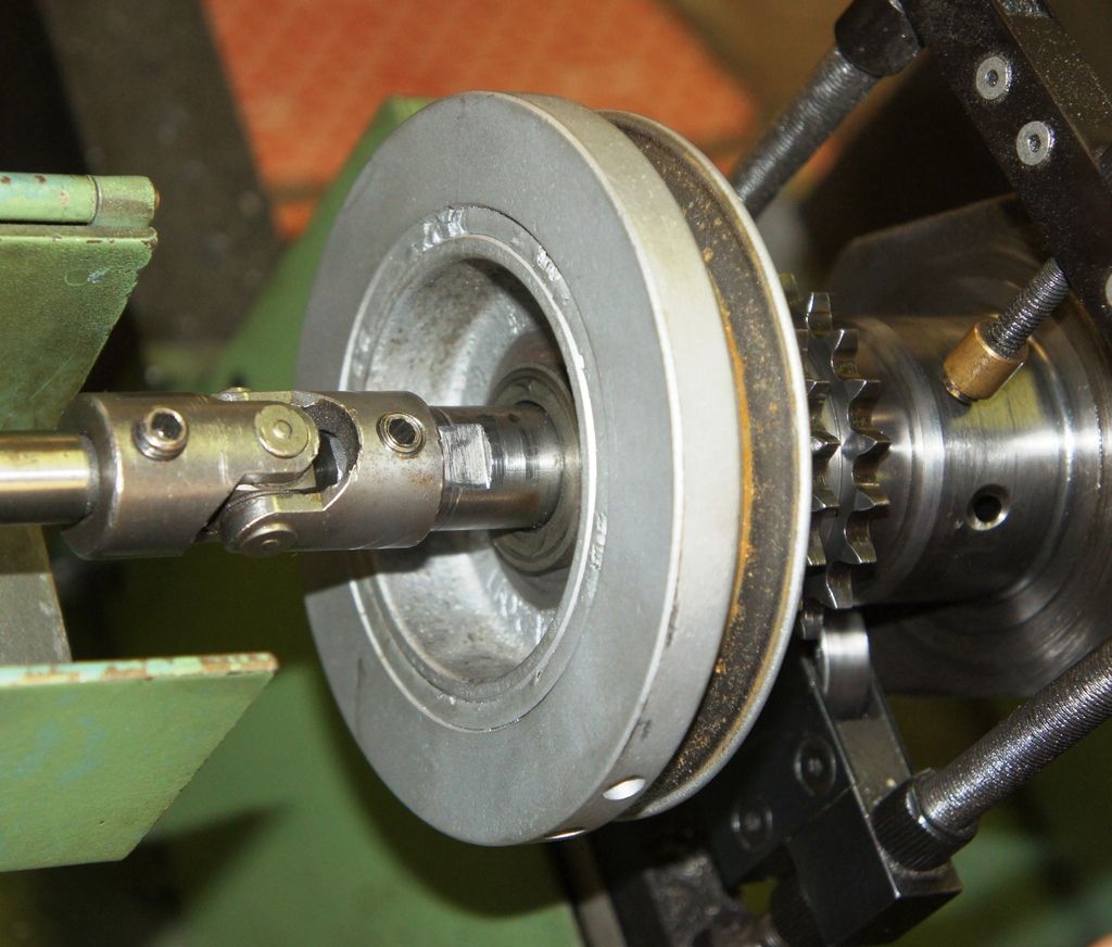
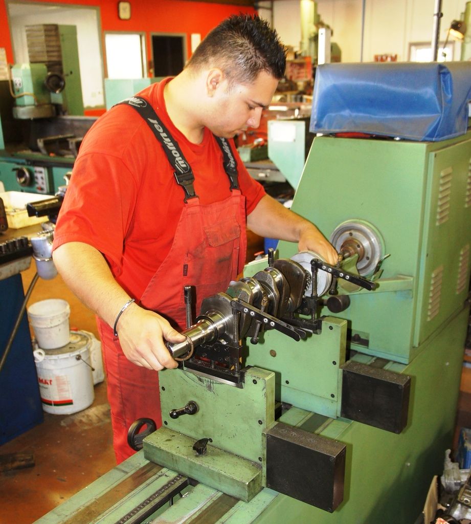
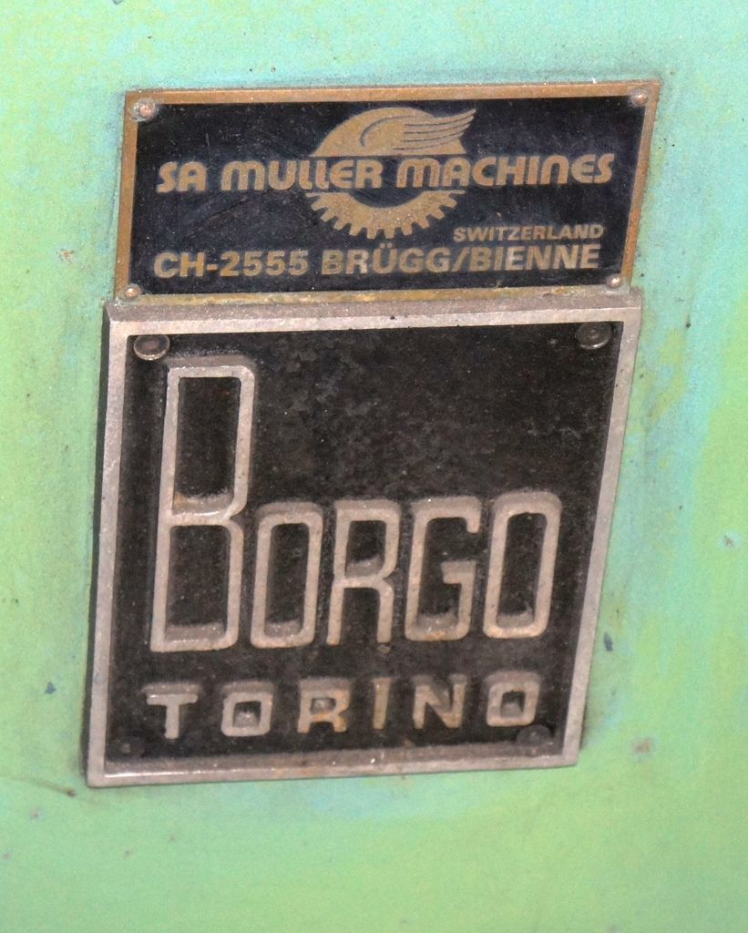
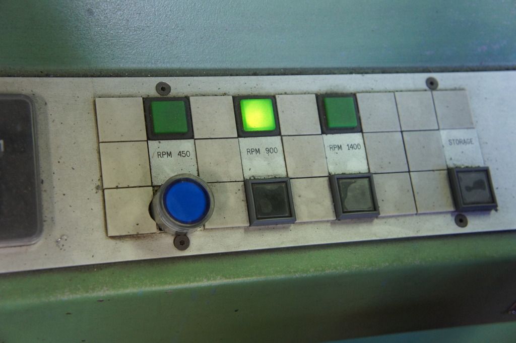
The BORGO machine has 3 speed ranges - 450, 900, 1400.
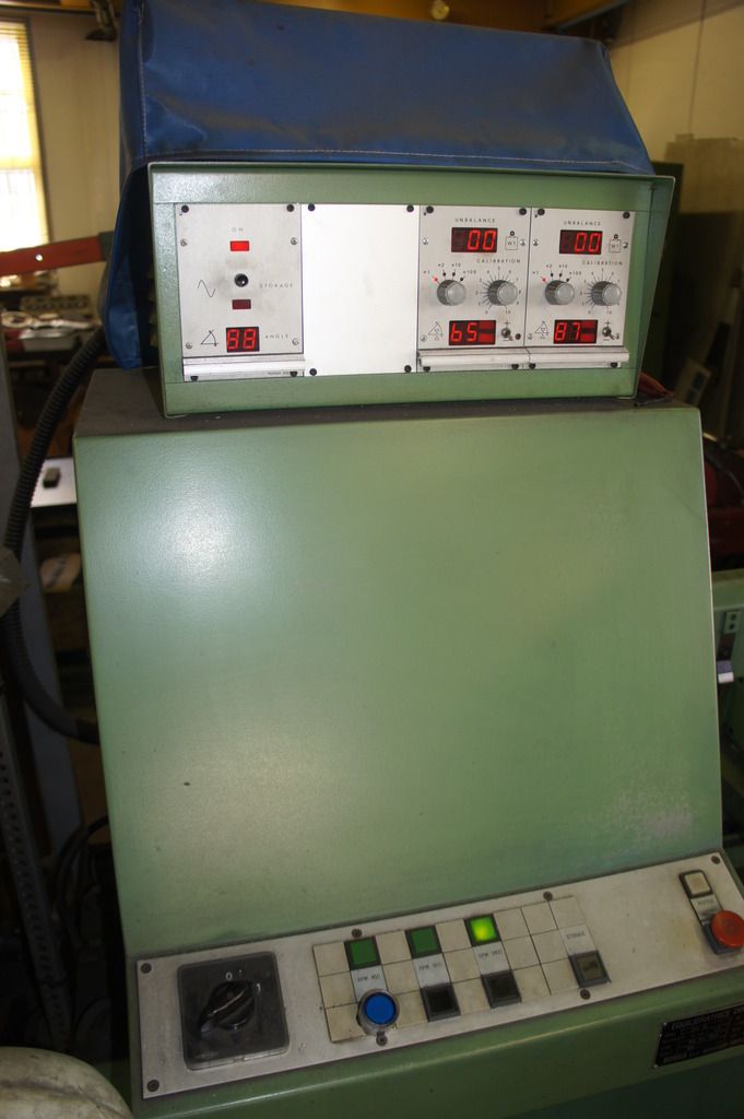
You start at 450 and balance the crank on the LH and RH ends (there are two "soft" or "floating" bearing carriers), then go up to 900 and carry out the same procedure, then 1400 and repeat.
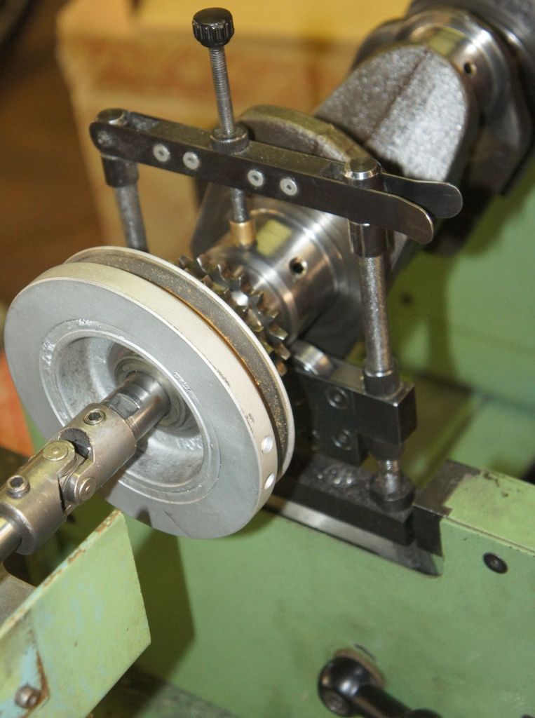
The idea is that each speed throws up different harmonics and if you can balance out all the wobbles at all 3 speeds then you're on your way to a better engine ; don't ask me why it doesn't run at 8.000 rpm - probably because the electronics can't cope, and if the crank flew off the supports it would kill someone whereas at 1400 you only lose an arm and the workshop window.
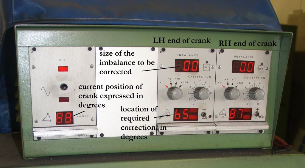
The read-outs show current angular crank position, and the "imbalance" measured and the angle at which it occurs.
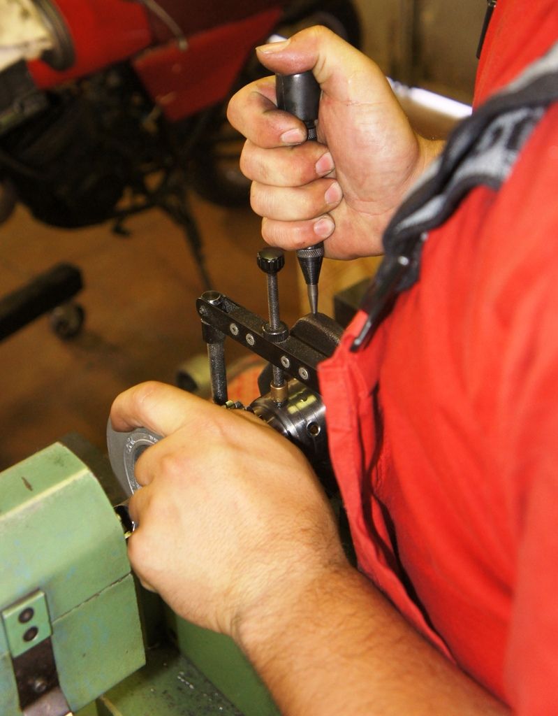
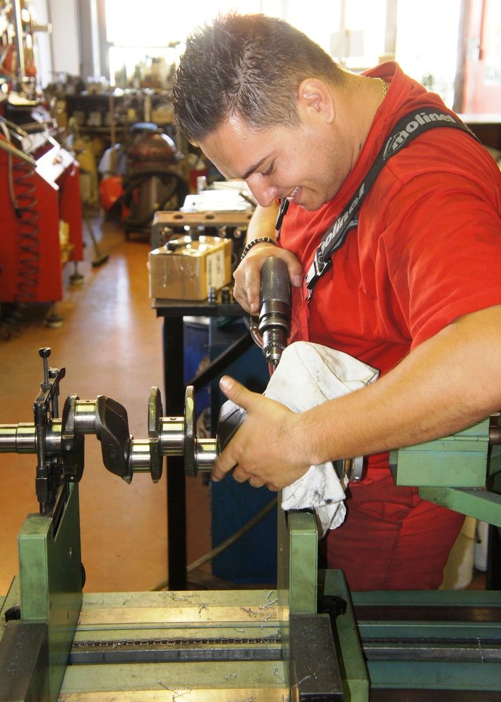
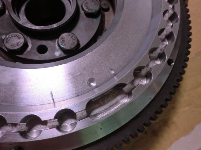
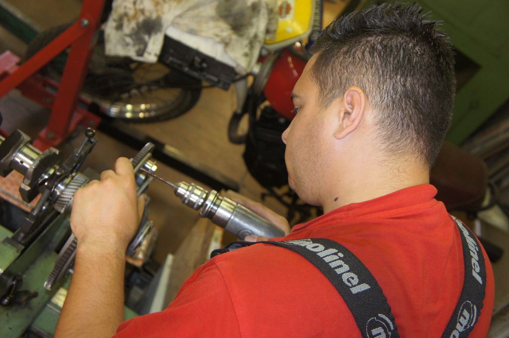
You then drill out a certain amount of metal at the given angular position - ie : automatic centre-punch followed by - in our case - a 5mm bit in an air-drill.
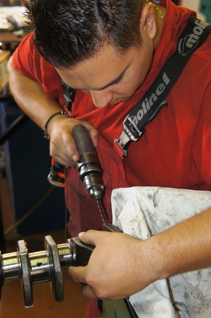
The depth of the hole is a seat-of-the-pants judgement by the operator, based on what radius he's drilling at (flywheel webs are of varying section) and how big the number on the top line is that he's trying to correct.
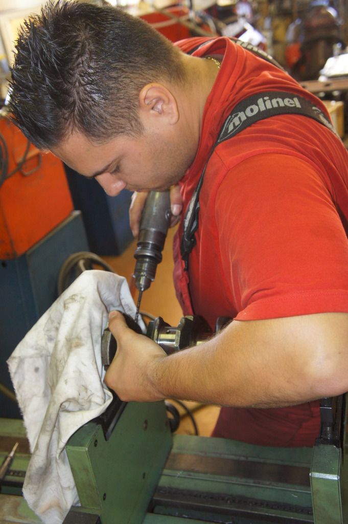
Julian never over-shot his drilling and took at most 3 stabs at the hole to chase the imbalance figure down to zero.
This is the 450 rpm read-out when we started :
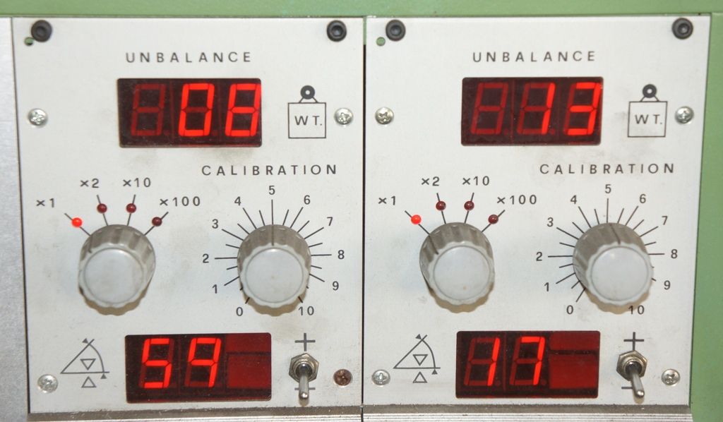
ie - 8 "units" out at 89° on the LH end, and 13 "units" out at 17°
After some hole-drilling, we get :
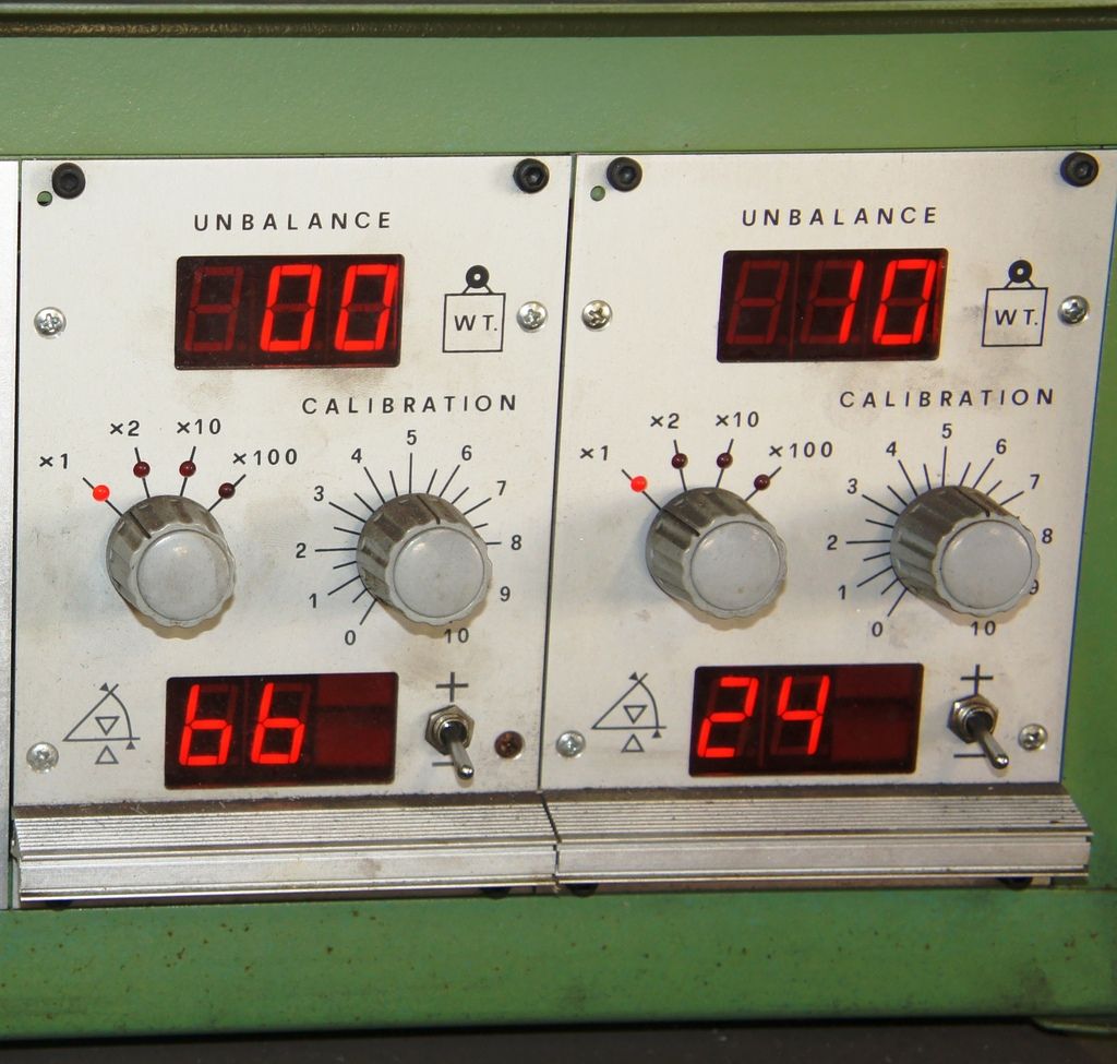
ie - we're down to zero on the LH end, but still 10 to go at 24° on the RH end.
Bit more drilling to get this :
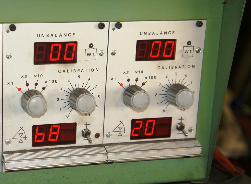
Both LH and RH down to zero.
So then it's up to 900 rpm :
and now we see we need :
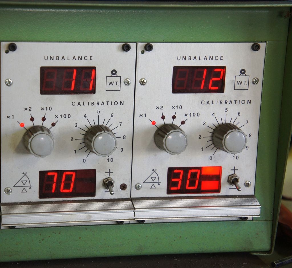
11 off at 70° and 12 off at 30°
and at 1400 it was 08 off at 70° and 21 off at 35°
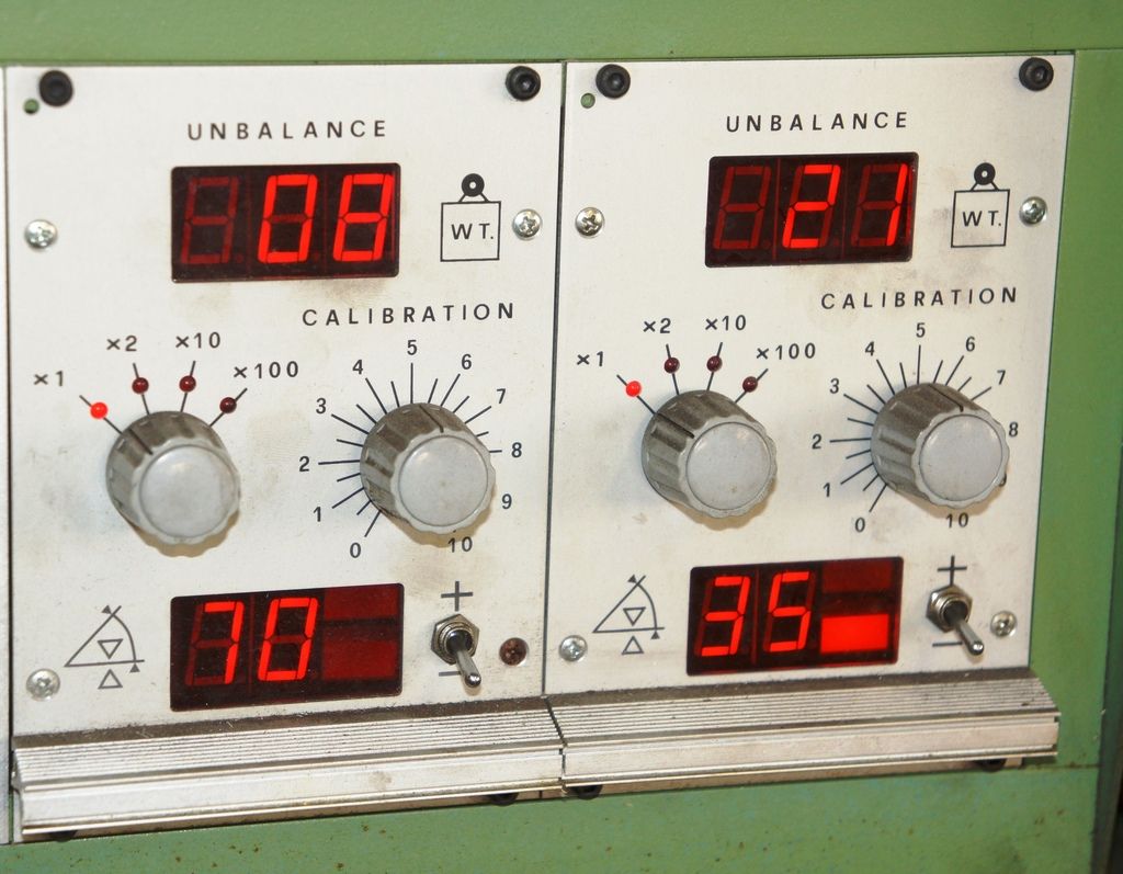
and once it's zero LH and RH at 1.400, you go back to 900 - and maybe correct something again - and to 450 - and maybe correct etc etc
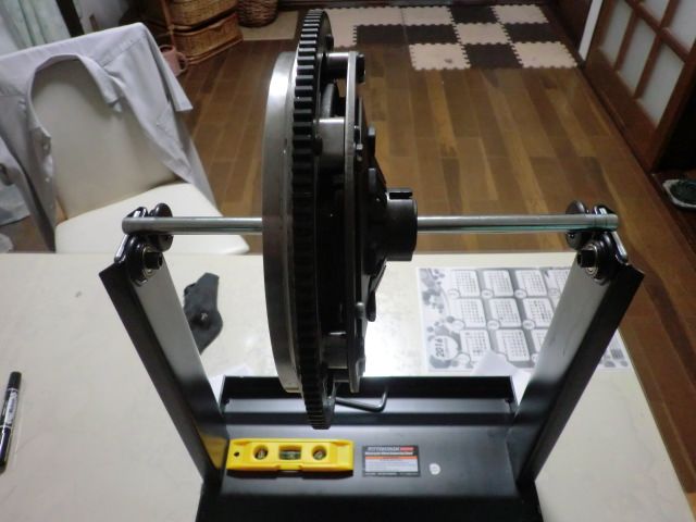
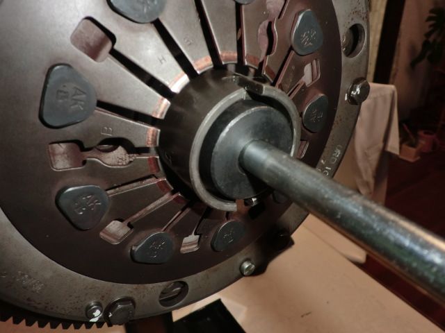
Once we were happy with just the crank, I built up the Primary Gear, washers, circlips etc and fitted the Flywheel, Cluch Back-Plate, INCLUDING the Back-Plate and all the (numbered and marked) straps and bolts and spacers, all bolted-up with the flywheel bolt and stepped washer.
Now this is likely to raise a few screams, and I'll be interested to hear the reasoning - as long as you understand what follows.
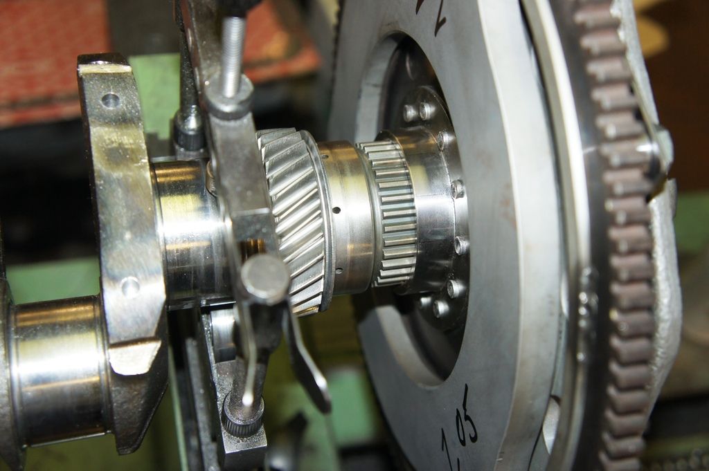
The Back-Plate has the potential (1.77kg here) to be fitted in various positions that can be at least 0.2mm between each other, which (1770 divided by 0.2) is 350 gramme.mm of imbalance, so I prefer to centre it as best I can using feeler guages and believe that by NOT subsequently removing the strap-to-flywheel bolts and by using the feeler-gauages again I can build back up the flywheel and clutch assembly to that same position when I assemble the engine definitively. The best we could get was 1.05, 1.10, and 1.15 - but bear in mind these are repeatable gaps.
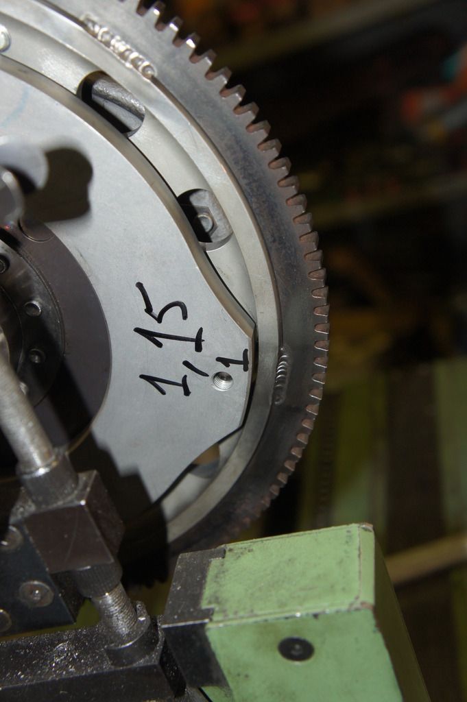
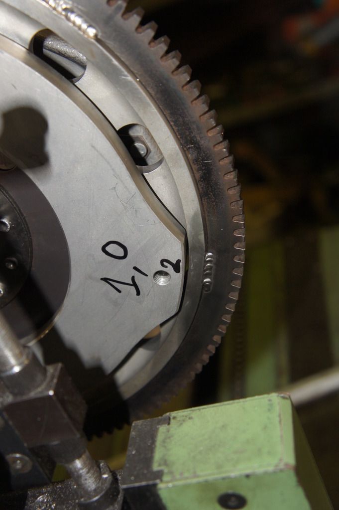
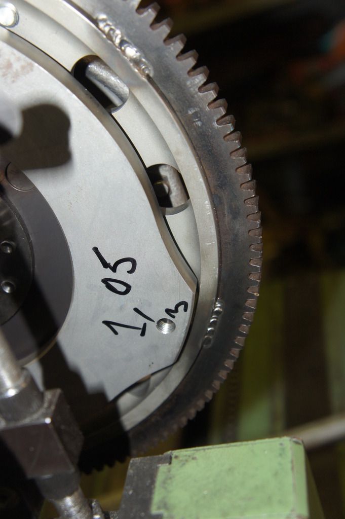
The idea that the clutch plate "never ends up in the same position" is true, but a) it weighs bugger all, b) it's industrially manufactured from symmetrical and regular identical parts, c) it's of a relatively small diameter, and d) any wear it suffers will be symmetrical.
So I believe including it in the balancing can never be more inaccurate than the balancing would have been without it (think about it ?) - and its presence enables you to clamp the back-plate (fat, heavy, big diameter) accurately and firmly in the position in which it will be running when the engine is running.
The flywheel had already been balanced by itself, by the supplier, and the small tweak seen here that was required to finalise the balancing of the complete crank/flywheel/clutch assembly would seem to confirm that the back-plate cannot be assumed to have no effect on the flywheel/clutch balance.
What was most noticeable, and Julian confirmed this, was that as the crank got better and better balanced, it took longer and longer to slow down after being spun on the machine.
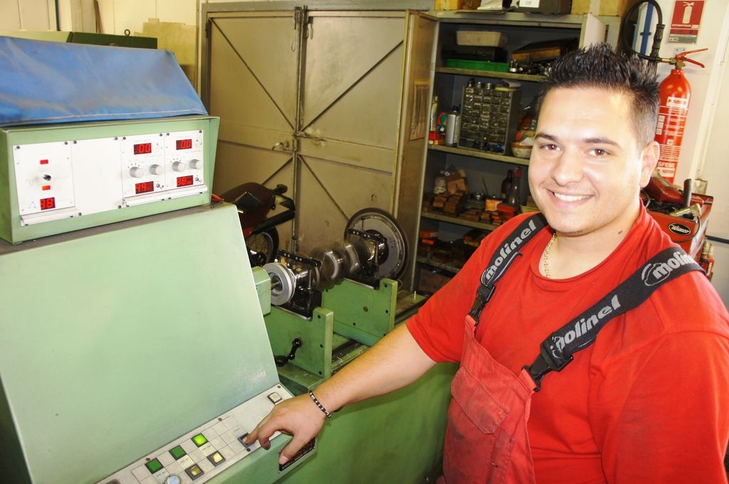
Here you can see the finished crank complete with all the clutch components spinning at 1.400 rpm, with all the imbalances shown at zero - this is as good as you can get on this machine.
Plus the guy who does the work gets to look happy with what he has done !
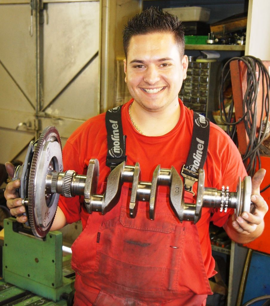
Does any of this matter on a car that will only be revved to 6.500 rpm ? Not sure, but it sure is satisfying .................


