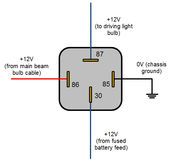
You normally have 4 terminals on a standard relay (There are relays with more but were dealing with the std 4 terminal type here)
This takes the load out of old switches as they are only then switching the relay current.
85 - 86 - 87 - 30
85 = The earth connection to the body to make the relay switch
86 = The switched 12v feed from either a on/off switch or a feed from a headlight main beam or similar
30 = The main feed into the relay from the starter solenoid or another 12v pick up point (Fused for anything other than Headlights) Headlights double up on the relays - 2 for l/r dip beam 2 for l/r main beam if you wish like the rallys cars.
87 = the relay switched feed out to lights or anything else, fuel pumps/amps/fans ...

The Tamping Diode will always be between terminals 85 and 86, used to prevent the relay switching back on by its self
Edited by KernowCooper, 03 August 2014 - 10:10 PM.


