Spi Aux Cooling Fan Wiring Help
#1

Posted 02 August 2011 - 11:22 PM
After almost a year almost everything is fixed on it but now with the summer months here giving us ambient temps between 35-40C over the past month I really need to get my auxiliary electric cooling fan working so I don't have to cringe each time I turn the key off and hear the coolant boiling inside the radiator making it's way to the overflow tank. No steam, no blown cap (yet), runs fine just the standard heat soak from stop and go traffic.
checked the in cabin fuse before all of this, it's good (think it's 9B offhand) though I don't know if a multimeter should get any voltage off the pins without the fuse in it?
I pulled the plug from the fan and hooked it up to a DC amp with alligator clips and jumped the thermostatic ground wires and the fan spins, so that part works.
Multimeter on the other end of the plug gives no juice with key on, so from here on back there is a problem and need some additional assistance.
I don't know if the wiring has been redone outside of rover spec but can assume it's a maybe due to the amount of wrapped electrical tape around everything (unless this was standard hat). From what I can see the wires coming from the power side of the fan plug assembly go into a larger bundle wrapped in plastic conduit back to the firewall where it runs to about the mid point then disappears behind the dash.
Before I start cutting bundles, removing this and that I wanted to know if anyone knew the true wiring path this "should" be going.
Wire colors from the power plug was black/green stripe // black
I did see another similar post from Sprocket about a relay could be stuck open or closed, not sure if this could be in the wiring path but if it is what I should be looking for I need to know what it looks like and where to find it.
I am no electrician but if described in basic terms (pictures are extremely helpful) I should be able to figure it out with help from the experts here.
-James
#2

Posted 02 August 2011 - 11:33 PM
someone'l be along who probably knows a better solution, my idea is a last resort really!
#3

Posted 03 August 2011 - 02:08 PM
#4

Posted 03 August 2011 - 03:34 PM
My brothers 95 SPi had a dead aux fan. When jumped it worked fine. I tried everything until I found that one of the connections on the relay (on the firewall) was rotted out and not connected. The wire was still sitting in the correct spot and looked fine but when I pulled the relay and looked at the wires connecters, that one was totally rusted out. Replaced it and the fan works a treat now.
Are you referring the yellow blocks right along the firewall on the right side? if so which one does the fan run through as I have two yellow blocks and one large black multi-wire plug in that general area (not sure if the wire color changes from here to there esp if it's not stock)
-James
#5

Posted 03 August 2011 - 03:56 PM
My brothers 95 SPi had a dead aux fan. When jumped it worked fine. I tried everything until I found that one of the connections on the relay (on the firewall) was rotted out and not connected. The wire was still sitting in the correct spot and looked fine but when I pulled the relay and looked at the wires connecters, that one was totally rusted out. Replaced it and the fan works a treat now.
Are you referring the yellow blocks right along the firewall on the right side? if so which one does the fan run through as I have two yellow blocks and one large black multi-wire plug in that general area (not sure if the wire color changes from here to there esp if it's not stock)
-James
I think I found it, just noticed Sprockets main guide had it's pictures restored last week (WOOHOO!) and there is a pic of the yellow relay nearest the inertia switch being labeled as the electric radiator fan relay.
I'll check that out and see what I find.
-J
#6

Posted 03 August 2011 - 10:48 PM

#7

Posted 04 August 2011 - 12:44 AM
I actually got the fan to power on for a short second from the junction point where the relay plugs in but was mezmorized a little too much and forgot which pins I was on, then my portable dc amp shorted out a little after that point (really moist here and had heavy condensation on it) so I couldn't repeat my feat.
Multimeter results are as follows (using the numbered points per the relay drawing on itself):
key off:
30 and 87 = 12.6v
30 and 85 = 9.8v
key on:
30 and 87 = 12.5v
30 and 85 = 9.7v
I'm a little confused as to what the relay box does? is it something like a built-in on/off switch for a circuit if it senses a particular behavior?
I have other relays (some new some not) and tried them in replacement but still didn't make a difference.
I'm not sure what kind of results should be expected from my multimeter numbers and if they are considered normal or not
#8

Posted 04 August 2011 - 11:33 PM
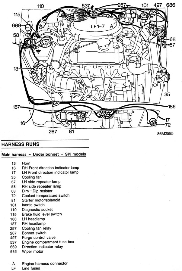
with key on 12v from Fuse B4 isn't making it Relay (257) point 86, thus not engerizing the relay to connect 30 to 87 and sending power to the fan.
multimeter has 12v at the fuse but notta at 86 where it ends up.
Seeing as the wiring is a literal rats nest of plastic conduit and duct tape all over the place, I think it would be easier to run a complete new wire from the block to the relay.
#9

Posted 05 August 2011 - 12:02 AM
The radiator switch grounds the solenoid's coil to switch on the fan, both the fan & switch are fused independently.
Fuse box - green/orange - relay - green/white - switch
Line fuse - purple - relay - black/green - motor
#10

Posted 05 August 2011 - 12:20 AM
Think I found the problem,
with key on 12v from Fuse B4 isn't making it Relay (257) point 86, thus not engerizing the relay to connect 30 to 87 and sending power to the fan.
multimeter has 12v at the fuse but notta at 86 where it ends up.
Seeing as the wiring is a literal rats nest of plastic conduit and duct tape all over the place, I think it would be easier to run a complete new wire from the block to the relay.
Hi,
Looking at page 27 of the following PDF, it looks like fuse B4 is fed from relay 685 output 87. Have you checked that relay?
http://www.theminifo...x...st&id=68240
Relay 685 (connector 214) is located in page 140 of the following PDF
http://www.theminifo...x...st&id=68242
Hope that helps,
Ivan
#11

Posted 05 August 2011 - 11:58 AM
Think I found the problem,
with key on 12v from Fuse B4 isn't making it Relay (257) point 86, thus not engerizing the relay to connect 30 to 87 and sending power to the fan.
multimeter has 12v at the fuse but notta at 86 where it ends up.
Seeing as the wiring is a literal rats nest of plastic conduit and duct tape all over the place, I think it would be easier to run a complete new wire from the block to the relay.
Hi,
Looking at page 27 of the following PDF, it looks like fuse B4 is fed from relay 685 output 87. Have you checked that relay?
http://www.theminifo...x...st&id=68240
Relay 685 (connector 214) is located in page 140 of the following PDF
http://www.theminifo...x...st&id=68242
Hope that helps,
Ivan
685 is working as it's supplying 12v to the B4 location with key on (yanked out the fusebox last night) with fuse in it is passing on current to the green/white wire toward the relay 257 point 86 but never gets there. 685 looks to also power my wipers/washers/heater motor/radio/ac blower as well and those are all functioning fine (key on of course).
#12

Posted 05 August 2011 - 01:14 PM
Think I found the problem,
with key on 12v from Fuse B4 isn't making it Relay (257) point 86, thus not engerizing the relay to connect 30 to 87 and sending power to the fan.
multimeter has 12v at the fuse but notta at 86 where it ends up.
Seeing as the wiring is a literal rats nest of plastic conduit and duct tape all over the place, I think it would be easier to run a complete new wire from the block to the relay.
Hi,
Looking at page 27 of the following PDF, it looks like fuse B4 is fed from relay 685 output 87. Have you checked that relay?
http://www.theminifo...x...st&id=68240
Relay 685 (connector 214) is located in page 140 of the following PDF
http://www.theminifo...x...st&id=68242
Hope that helps,
Ivan
685 is working as it's supplying 12v to the B4 location with key on (yanked out the fusebox last night) with fuse in it is passing on current to the green/white wire toward the relay 257 point 86 but never gets there. 685 looks to also power my wipers/washers/heater motor/radio/ac blower as well and those are all functioning fine (key on of course).
Sorry, I misunderstood. Then it seems that the wire from splice SJ14 to terminal 86 on relay 257 is interrupted since the radio and everything else works. Your initial assessment might be the best way to go.
Ivan
#13

Posted 06 August 2011 - 03:20 AM
Think I found the problem,
with key on 12v from Fuse B4 isn't making it Relay (257) point 86, thus not engerizing the relay to connect 30 to 87 and sending power to the fan.
multimeter has 12v at the fuse but notta at 86 where it ends up.
Seeing as the wiring is a literal rats nest of plastic conduit and duct tape all over the place, I think it would be easier to run a complete new wire from the block to the relay.
Hi,
Looking at page 27 of the following PDF, it looks like fuse B4 is fed from relay 685 output 87. Have you checked that relay?
http://www.theminifo...x...st&id=68240
Relay 685 (connector 214) is located in page 140 of the following PDF
http://www.theminifo...x...st&id=68242
Hope that helps,
Ivan
685 is working as it's supplying 12v to the B4 location with key on (yanked out the fusebox last night) with fuse in it is passing on current to the green/white wire toward the relay 257 point 86 but never gets there. 685 looks to also power my wipers/washers/heater motor/radio/ac blower as well and those are all functioning fine (key on of course).
Sorry, I misunderstood. Then it seems that the wire from splice SJ14 to terminal 86 on relay 257 is interrupted since the radio and everything else works. Your initial assessment might be the best way to go.
Ivan
It's ok Ivan.
all fixed now, ran a new wire and tapped the current one after B4 fuse and just before 257 on terminal 86. Put the relay back in, jumped thermostatic switch, key on and fan whirring away! disconnect thermostatic jumper, fans stops as it should (clearly hearing the relay click).
Thanks everyone for your help on this.
James
1 user(s) are reading this topic
0 members, 1 guests, 0 anonymous users


