Timing A Cam With A Dti, How Its Done...
#1
Posted 16 December 2011 - 06:24 PM
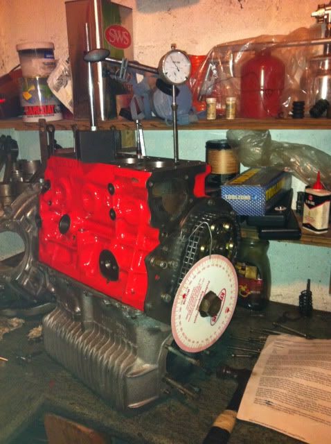
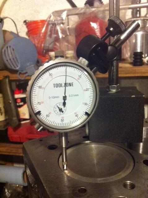
So first thing to do is to set the DTI up on piston number 1, Thats the one nearest to the front, (water pump end), of the block. Set it with a small preload, you will get much more accuracy with the readings
Turn the crank untill the piston is at TDC...you will see the dial spin round and then stop.it will then go back the other way..turn the crank untill the dial reaches the point where it changes direction. This point is TDC. Now zero the dial and move the crank back and fore a small amount to check its at zero on TDC.
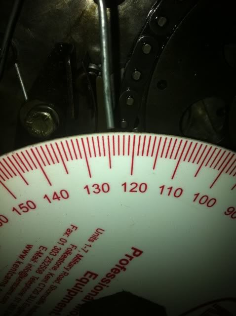
Next you can loosly fit the protractor wheel to the end of the crank and fit a bit of stiff wire. I use a bit of fence wire and attach it to the timing cover bolt. Turn the wheel so its TOP mark is uppermost and tighten the bolt so its fixed to the crank..Then move the bit of wire untill it points to the TOP mark..
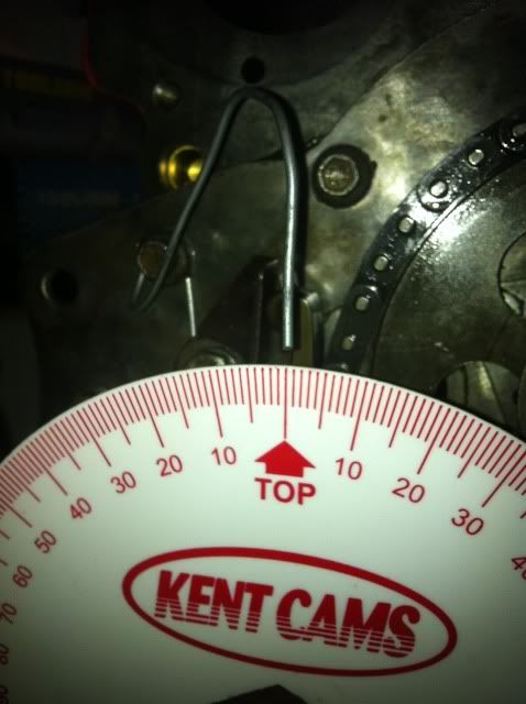
Ok so now you are at TDC with a zero reading on the protractor wheel...
Next you pop a push rod down the number one inlet hole, (second one from the front) and make sure its seated in the follower. Then you can set up your DTI onto the push rod..again with a little preload.
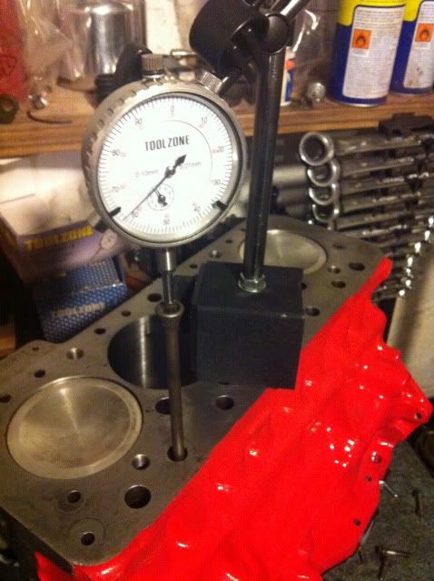
Dont wory about the reading on the DTI at this stage. Right so now you need to turn the crank forwards, Thats clockwise when looking at the front, You will see the DTI spin round a few times and then slow down and stop. move the crank back and fore untill you are sure the needle is at the point where it changes direction. Again zero the DTI. The cam is now at maximum lift on number 1 inlet .
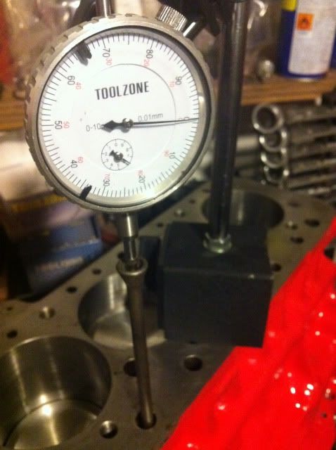
My protractor wheel was reading 112deg ATDC at this point of maximum lift.
Turn the crank backwards untill the DTI reads 0.025"
Next you need to slowly turn the crank forwards until the DTI reads 0.005" mark..Mine is a metric DTI so the reading is 0.127mm. you will find this quite tricky to get exact and a bit of forwards and backwards movement on the crank will be required to get the reading spot on, but dont cheat here as its critical to your timing.
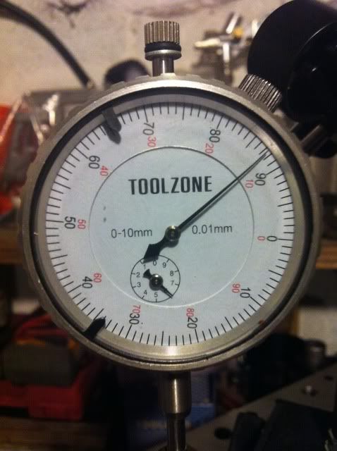
Note that because the crank has actually moved slightlybackwards at this stage my DTI has a reverse reading, but its 0.127mm from the zero point.
Once you have got it spot on then take a note of the reading on the protractor wheel
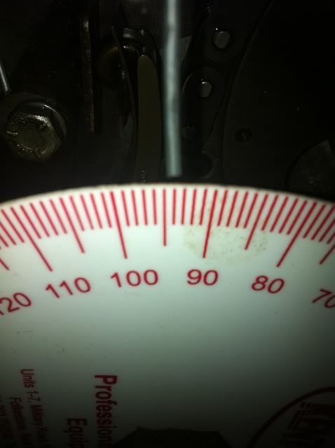
Mine shows 94 deg.
Next you continue to turn the crank forwards untill the DTI goes back to the 0.005" mark. it will move away and go back as the cam lobe goes over the max lift and drops off the other side..then you can take another reading off the wheel..
Mine says 124.5 deg..
Right so now its time for the maths...you add the two wheel readings together...94+124.5 = 218.5
next you divide that by 2...so 218.5 divided by 2 equals 109.25 deg...And thats what my cam its timed in at 109.25 deg after TDC..
Now considering the max lift reading was 112deg..thats my cam timed in 3 deg advanced. The Spec for the MG cam from Rover says it should be 110 deg ATDC. So im pretty much bang on the money at dot to dot..I could retard it with offset woodruf keys by a few degrees and maybe gain a small amount of torque, but im not going to bother with this spec of engine. Dot to dot turns out to be fine.
#2
Posted 16 December 2011 - 08:04 PM
Great work
#3
Posted 16 December 2011 - 10:04 PM
#4
Posted 17 December 2011 - 10:30 AM
It was done as part of my Engine build and Danny1 asked to see how I do it, then Ethel suggested I start a new thread with just this bit...I hope it helps a few people. And thanks for the nice reply. It makes it all worth while..or pinned to the faq?
#5
Posted 17 December 2011 - 07:31 PM
#6
Posted 17 December 2011 - 07:56 PM
this is really usefull information for any one wanting to build a thred, as it very much is an idiots guide, id feel happy to let my mrs's build an engine after reading this, and shes a woman
I quite hope that your Mrs's is a Woman!Haha!
#7
Posted 17 December 2011 - 08:24 PM
#8
Posted 17 December 2011 - 09:38 PM
#9
Posted 20 February 2012 - 08:38 PM
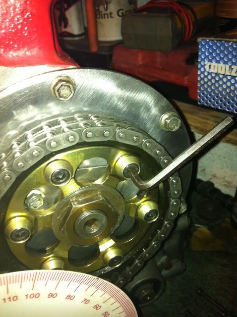
So I loosened the alan keys and gave it a quick tap ant clockwise...Once I checked it again I found it was miles off at 114deg ATDC..So another adjustment, (two taps clockwise)..and then checked again, 105deg ATDC...which is good enough for me..
So basicly the timing is exactly the same procedure as the non vernier type gears...but with the abillity to make easy adjustments without removing the timing gears and faffing around with offset woodruf keys..
#10
Posted 22 February 2012 - 02:29 PM
Just a quick question how do you find what your cam should be timed in at?
#11
Posted 22 February 2012 - 03:17 PM
The method of finding tdc (and maximum cam lift*) may well suffice, but it can be done more accurately...
When the piston is near tdc the angular change of the crank is at it's largest in relation to how far the piston moves up & down the bore - visualise a pea rolling off the top of a football and you'll get the idea. Now, once you've found roughly where the piston changes direction you can turn the crank so it's an equal distance down the bore (using the dti) on either side of tdc. Read the protractor each time and tdc will be found in the middle of that angle. Always turn the engine in the right direction to get to your readings to eliminate any slack.
* This won't be strictly true if you have an assymetric cam - which might also be a reason for the 5 'n 25thou bit, but only if that's correct for your particular cam.
By all means build your engine with as much care as you can but, thanks to the A Series's siamese ports the best cam timing for the outer two cylinders won't be the best for the inner two so it isn't as critical as on other lumps. Unless, of course, you have a flash scatter pattern cam that optimises for all your cylinders.
#12
Posted 22 February 2012 - 04:27 PM
James...Yes the timing numbers came with the cam..
To anyone who has the RE 13 OT cam please use 101.5 - 102deg ATDC as your timing if useing the push rod method as I have shown in the pictures...104.5 deg ATDC IS THE FIGURE YOU NEED IF YOU USE THE DTI ON THE VALVE GEAR.. sorry for any confusion...this new forum wont let me edit my mistake..ARRGHHH!!
#13
Posted 28 March 2012 - 08:29 AM
The measurement shows the relationship between crankshaft and camshaft, but if it is outside the recommended limits, what do I do? The concept of an offset Woodruf key completely escapes me - in my mind's eye, all I can imagine is a slot on shaft and pulley which allows the key to lock the two in alignment. How can the key change that alignment please?
Obviously, I have missed something blindingly obvious (it wouldn't be the first time) but while I can see how a vernier gear allows simple adjustment - at a price - I am unclear how it's done with the more common duplex timing unit.
As always, advice appreciated.
Bob
#14
Posted 28 March 2012 - 03:42 PM
The offset woodruf key is a simple device that slots into the normal groove in the cam but then allows the cam sprocket to slide over it at a different angle, therefore changing the angle of the cam in relation to the crank by whatever degrees you need your cam adjusted.
Hope this helps...Im not brilliant at explaining stuff and dont have any pictures to back up my comments...but maybe someone will post a picture to show what I mean..
Cheers
Andy.
Edited by AndyMiniMad., 28 March 2012 - 03:43 PM.
#15
Posted 28 March 2012 - 07:18 PM
But, you have shown us how to determine the relationship of cam to crank. I guess I have to hope that mine will be within a degree or two but if not I will have to buy one of these magic keys to get it right.
One last question please. Are the keys positive and negative or can you reverse them to alter the setting one way or another? Or, I guess one could go on the cam drive or the crank drive to get a different balance between the two.
And if my ignorance brings a smile to one or two of you - that's no bad thing.
Bob
1 user(s) are reading this topic
0 members, 1 guests, 0 anonymous users